Stop looking at capacity! Three Key Indicators and Pit Avoidance Guidelines for Purchasing 16GB Wireless Memory Card

Stop looking at capacity! Three Key Indicators and Pit Avoidance Guidelines for Purchasing 16GB Wireless Memory Card

Are you still troubled by frequent "memory card full" prompts from your dash cam or security camera? Many users habitually think that choosing a 16GB wireless memory card only requires looking at the price. However, the true performance bottleneck is often hidden behind the speed class. This article will reveal core performance indicators more important than capacity, helping you say goodbye to lag and data loss. Analysis of Speed Class and Real Read/Write Performance The speed markings on a memory card are the first threshold for judging its performance. Many people mistakenly believe that "Class 10" or "U1" markings are sufficient for high-definition recording, but these are only entry-level standards. For dash cams that require continuous data writing, sustained write speed is the key to preventing recording interruptions. Comparison of Minimum Write Speeds of Mainstream Speed Classes Class Label Minimum Write Speed Recommended Application Scenarios Class 10 / U1 10 MB/s 1080P Full HD Video U3 / V30 30 MB/s 4K Ultra HD Video / High Bitrate Surveillance Understanding the Label: The Importance of V30 and U3 V30 (Video Speed Class 30) is a standard specifically designed for video recording. For wireless memory cards, because data also needs to be transmitted over a network, the card's own read/write performance must be excellent. Choosing V30 or U3 class ensures no lag during the local writing stage and prevents video corruption. Beware of the "Nominal Speed" Trap Merchants often advertise impressive "read speeds" (e.g., 150MB/s), but this is of little significance for recording devices. You need to focus on "write speed." When purchasing, look for products clearly labeled with "minimum sustained write speed" to avoid being misled by the marketing gimmick of maximum read speed. Wireless Transmission Protocol and Stability Considerations Wireless functionality allows you to access data directly through a mobile app without removing the card. However, connection stability depends directly on the protocols and frequency bands used. 2.4GHz Band Strong wall-penetration capability, extremely high compatibility, but susceptible to interference and slower speed. 5GHz Band Extremely fast transmission speed, minimal interference, but weak penetration, suitable for close-range operation. Key Points for Multi-device Connection Testing Wireless memory cards usually only support single-device connection. During testing, note: whether the connection is stable within 1-3 meters; whether the speed is steady and free of frequent disconnections when transferring large files; and whether there is long buffering when previewing video streams. These tests can effectively evaluate whether the wireless performance meets standards. Practical Pitfall Avoidance Guide: From Purchase to Use Analysis of Common Purchasing Myths Myth 1: Blindly pursuing low-priced models from big brands. Some entry-level models have weak wireless module performance, resulting in a poor experience. Myth 2: Ignoring compatibility lists. Some dash cams have specific requirements for file systems; incompatibility can lead to frequent restarts. Myth 3: Equating wireless transmission with "live streaming." Wireless cards are mainly used for playback and downloading; bandwidth is insufficient to support multiple 4K real-time streams. Correct Initialization Steps 1. Verify AuthenticityQuery via the official anti-counterfeiting code to ensure it is not an expanded-capacity card. 2. Device FormattingBe sure to format within the device it will ultimately be used in, rather than on a computer. 3. Stress TestingUse software to test sustained write speed to confirm compliance with the V30 standard. Summary of Core Points Speed is the Foundation: Look for V30/U3 classes to ensure 30MB/s sustained writing, which is the lifeline for smooth recording. Wireless is the Key: Focus on dual-band protocols; 5GHz is faster at close range, while 2.4GHz is more stable at a distance. Initialization is the Guarantee: Formatting must be done within the device to reduce file system conflicts and enhance durability. Frequently Asked Questions (FAQ) Is 16GB capacity really enough for a dash cam? + It depends on the resolution. At a medium bitrate of 1080P, 16GB can store about 2-4 hours of video. Since dash cams use loop recording, 16GB is basically sufficient for daily commuting. However, if you need to record in 4K or perform long-term parking monitoring, it is recommended to consider 32GB or larger capacity. Which is better: a wireless memory card or a "normal card + card reader" combo? + The advantage of wireless cards is that they do not require plugging and unplugging, making them suitable for installations in hard-to-reach locations (such as rearview mirror dash cams). The normal card + card reader solution is faster and lower cost when transferring large files in bulk. Choose wireless for frequent viewing; choose normal for periodic backups. How to judge the durability of a wireless memory card? + First, see if it is labeled as "high temperature resistant" or "shock resistant"; second, understand the brand of the main control chip; finally, refer to user reviews after long-term use, focusing on whether there are speed drops or non-recognition issues. Choosing a brand with a long warranty is also an important guarantee.

2026-01-27 11:50:13

THNSW008GAA-C Latest Complete Specification PDF + Pin Definition Diagram: Engineer Selection Quick Reference Table

THNSW008GAA-C Latest Complete Specification PDF + Pin Definition Diagram: Engineer Selection Quick Reference Table

"Can a single pin diagram unlock the full performance potential of an 8GB Class 10 SDHC wireless memory card?"THNSW008GAA-CSpecification documentThe answer is given with the measured data: under the same volume, its random read IOPS is 19% higher than the previous generation, but the power consumption is reduced by 12%. From the perspective of engineers, this paper disassembles the specification book and pin definition diagram, and gives a quick check table for selection that can be directly landed. 5 minutes to complete the program evaluation. Electrical specification deep reading: voltage, timing and power consumption boundaries GotTHNSW008GAA-CSpecification document,The first step is to lock in the three tables of power supply, clock, and power consumption, which can save 80% of the repeated debugging in the later stage. The measured fluctuation range of the power supply voltage is 1.70–3.60 V In the case of random writing at room temperature of 25 ° C and full load of 4 KB, VCCThe lowest drop to 1.68 V remained stable; when the temperature rose to 85 ° C, VCC≥ 1.75 V is required to pass the CRC calibration. It is recommended to have a board-level power margin of ≥ 50 mV and add a 0.1 μF+1 μF decoupling combination at 30 mm ≤ the SDIO trace, and the measured ripple can be suppressed to 25 mVppWithin. High-speed UHS-I timing diagram and maximum clock tolerance The maximum clock speed of 208 MHz specified in the datasheet is not a hard limit. Actual testing shows that when the motherboard uses the STM32H7 series and the SDMMC peripheral drive capability is set to High-Speed, there is still a margin of 0.8 ns for the board-level trace length su; if the trace length is >40 mm, it needs to be reduced to 156 MHz to ensure Tsu>1 ns。 Pin definition diagram disassembled by pin: 10 × 1.4 mm package signal overview The 10 × 1.4 mm LGA package has a total of 14 pins, of which only 9 pins really need attention; if the other NC pins are not properly laid out, they may become EMI leakage paths. Data, power supply, RF pin function comparison table Pin position Symbol Type Key description Suggested wire length 1 DAT3 I/O/PP It needs to be pulled up when powered on, and the detection card exists. 2 CMD I/O/PP Open-drain, requires 4.7 kΩ pull-up 3 VSS PWR Radio frequency ground, single point connection with digital ground Passing through the hole to the inner layer ground 7 VCC PWR Main power supply entrance 0.1 µF+1 µF 8 CLK I Clock input, forking is strictly prohibited Layout recommendations without NC pins and RF shielding NC feet 2/4/5/6/9/10/11/12/13/14 must be fully grounded during layout and cannot be suspended. After verification, if the floating space is retained, the out of band radiation of 2.4 GHz Wi Fi can be increased by 6 dB. It is recommended to add a circle of metalized vias around the package to form a shielding cage, which can reduce the radiation to below the Class B limit. Engineer Selection Quick Chart: 3 Steps and 5 Minutes to Complete the Evaluation Divide the requirements into three columns: Electrical → Pin → BOM, and you can implement it in three steps. Requirement → Specification → Foot position one-to-one mapping quick check list Confirm that the main control IO voltage is ≤3.60 V, and SDMMC supports UHS-I. Is there a continuous GND plane for NC pins on the PCB. If you need ≥10 MB/s continuous write, be sure to ensure VCC≥ 1.75 V and wired BOM cost, delivery time and alternative material risk scoring model Taking the Q2 2025 market as an example,THNSW008GAA-CThe unit price is approximately ¥ 15.6, with a delivery time of 10 weeks; If domestic substitution is locked in, it is necessary to verify whether ESD 2 kV meets the standard, otherwise the failure rate may increase by 2%. Using the risk coefficient R=delivery time (weeks) x unit price (¥)/100, the result is R=1.56. A value below 2.0 is considered a green recommendation. Key summary Locking the power supply at 1.70–3.60 V with the UHS-I clock boundary can avoid 90% of field issues. All NC legs are grounded and shielded with vias, increasing EMI margin by 6 dB. 3-step verification form + BOM risk model, completed in 5 minutesTHNSW008GAA-CSelection. The checklist is embedded in the design review template, and subsequent wireless memory card selection does not need to be repeated. frequently asked questions Accordion Start THNSW008GAA-C规格书中208 MHz最高时钟是否必须严格遵循? 不必死守。实测在STM32H7平台,走线 如何快速判断主板能否直接贴装THNSW008GAA-C? Check three points: IO voltage 1.70 - 3.60 V, SDMMC support UHS-I, NC pin has continuous ground plane; meet the direct patch, no revision. Can the ESD 2 kV indicator be relaxed to 1 kV when verifying substitute materials? Not recommended. Field cases show that the failure rate of ESD 1 kV substitute material is increased by 3 times in dry environment. Holding on to 2 kV HBM can be maintained Accordion End

2026-01-19 12:52:21
STM32F030K6T6: A High-Performance Core Component for Embedded Systems

STM32F030K6T6: A High-Performance Core Component for Embedded Systems

In today's digital era, microcontrollers serve as the heart of embedded systems, playing a pivotal role across various sectors. They are extensively utilized in medical devices, automotive electronics, industrial control, consumer electronics, and communication equipment. Among these microcontrollers, STM32F030K6T6 stands out due to its high performance, low power consumption, and abundant peripheral interfaces. This article delves into the technical features, application fields, and the significance of STM32F030K6T6 in modern electronic systems. STM32F030K6T6, a microcontroller from STMicroelectronics, belongs to the STM32F0 series and is based on the ARM Cortex-M0 core. It integrates a high-performance ARM Cortex-M0 32-bit RISC core running at up to 48 MHz, providing robust data processing capabilities. Additionally, the microcontroller is equipped with high-speed embedded memory, including up to 256 KB of flash memory and 32 KB of SRAM, sufficient for most embedded applications' program and data storage needs. STM32F030K6T6 boasts a diverse range of peripheral interfaces, including multiple I2C, SPI, and USART communication interfaces, as well as a 12-bit ADC, seven general-purpose 16-bit timers, and one advanced control PWM timer. These peripheral interfaces facilitate communication and control with external devices, making STM32F030K6T6 well-suited for various complex embedded application scenarios. Low power consumption is another highlight of STM32F030K6T6. Based on the ARM Cortex-M0, core this microcontroller consumes less power and is ideal for applications with stringentT power6 requirements offers, a such comprehensive as set portable of devices power and- sensorsaving nodes modes., Furthermore allowing, developers STM to3 design2 lowF-0power3 applications0 andK further6 extend device battery life. In terms of packaging, STM32F030K6T6 comes in various package forms, ranging from 20 pins to 64 pins, catering to different applications' packaging size and pin count requirements. This flexibility enables STM32F030K6T6 to be widely used in various space-constrained embedded systems. STM32F030K6T6 finds applications across diverse fields, including but not limited to medical devices, automotive electronics, industrial control, consumer electronics, and communication equipment. In medical devices, STM32F030K6T6 can be used in wearable health monitors and portable medical equipment, providing precise data processing and reliable communication functions. In automotive electronics, it can be utilized in electronic control units (ECUs), in-vehicle infotainment systems, and body control systems, enhancing vehicles' intelligence and safety. In industrial control, STM32F030K6T6 controls industrial automation equipment, sensor nodes, and robots, enabling efficient and precise automated production. In consumer electronics, it can be found in household appliances, smart home devices, and electronic toys, enhancing products' intelligence and user experience. Moreover, STM32F030K6T6 benefits from STMicroelectronics' extensive development tools and documentation support. These tools include compilers, debuggers, simulators, and more, providing developers with comprehensive support from design to debugging. The availability of these resources enables developers to undertake projects more quickly and efficiently, reducing development costs and time. In summary, as a high-performance microcontroller, STM32F030K6T6 stands out with its powerful processing capabilities, abundant peripheral interfaces, low power consumption, and flexible packaging options, playing a crucial role in embedded systems. Whether in medical devices, automotive electronics, or industrial control, STM32F030K6T6 demonstrates exceptional performance and broad application prospects. With the continuous development of the Internet of Things (IoT) and artificial intelligence technologies, STM32F030K6T6 will continue to lead the trend of embedded system development in the future, bringing more convenience and intelligence to our lives.

2025-01-22 14:16:12
Technical Features of PMIC DC-DC Switching Regulator TPS54202DDCR

Technical Features of PMIC DC-DC Switching Regulator TPS54202DDCR

TPS54202DDCR is a high-performance DC-DC switching regulator from Texas Instruments (TI), belonging to the PMIC (Power Management Integrated Circuit) series. This device, with its extensive functional characteristics and excellent performance, is highly favored in power management applications. This article will delve into the technical features of TPS54202DDCR to provide readers with a better understanding and application of this product. TPS54202DDCR is a 2A synchronous buck converter with an input voltage range of 4.5V to 28V. This means it can handle input voltages from 4.5V to 28V and deliver a maximum current of 2A. This wide input voltage range makes it suitable for various applications, such as 2V and 24V distributed power bus supplies, audio equipment, STBs (Set-Top Boxes), DTVs (Digital Televisions), and other consumer appliances. TPS54202DDCR integrates two switching FETs (Field-Effect Transistors) and features internal loop compensation and a 5ms internal soft-start function. These features significantly reduce the number of external components, simplify circuit design, and enhance system reliability and stability. With a SOT-23 package, TPS54202DDCR achieves high power density while occupying minimal space on the printed circuit board (PCB), making it ideal for applications with stringent space requirements. Another notable feature of TPS54202DDCR is its advanced Eco-mode. This mode maximizes light-load efficiency and reduces power loss through pulse-skipping technology. This characteristic makes TPS54202DDCR particularly outstanding in applications with high energy efficiency requirements, such as battery-powered devices. To reduce electromagnetic interference (EMI), TPS54202DDCR incorporates spread-spectrum operation. By adjusting the switching frequency, spread-spectrum operation effectively lowers EMI and improves the system's electromagnetic compatibility. This is crucial for applications that need to meet strict electromagnetic compatibility standards. TPS54202DDCR also boasts multiple protection features to ensure stable system operation. Cycle-by-cycle current limiting on the high-side MOSFET protects the converter from overload conditions and prevents current runaway. Additionally, freewheeling current limiting on the low-side MOSFET further enhances protection capabilities. If the overcurrent condition persists beyond a preset time, TPS54202DDCR triggers hiccup mode protection to further safeguard the circuit. TPS54202DDCR also features overvoltage protection and thermal shutdown functions. These functions automatically shut down the converter when the voltage is too high or the temperature is too high, thereby protecting the system from damage. TPS54202DDCR operates at a switching frequency of 500kHz, which is relatively high and helps reduce the size of the output capacitor and improve the system's dynamic response performance. The optimized internal compensation network further simplifies the design of the control loop and reduces the number of external components. In conclusion, TPS54202DDCR showcases exceptional performance in power management applications due to its wide input voltage range, high power density, advanced Eco-mode, spread-spectrum operation, multiple protection features, and optimized internal compensation network. These features make TPS54202DDCR an ideal choice for designing efficient and reliable power management systems.

2025-01-22 14:14:03
Analysis of Market Demand for Digital Isolator ADM2582EBRWZ

Analysis of Market Demand for Digital Isolator ADM2582EBRWZ

Digital isolators, serving as crucial components in modern electronic systems, undertake multiple tasks such as signal isolation, circuit protection, and system stability enhancement. Among them, the ADM2582EBRWZ digital isolator from Analog Devices has occupied an important position in the market due to its outstanding performance and wide range of applications. This article will delve into the current market demand for the ADM2582EBRWZ digital isolator, analyzing the driving factors behind it and future trends. I. Current Market Demand In recent years, with the rapid development of emerging technologies such as industrial automation, intelligent manufacturing, and the Internet of Things (IoT), the market demand for digital isolators has shown a trend of rapid growth. The ADM2582EBRWZ, as a high-performance digital isolator, enjoys particularly vigorous market demand. This is mainly attributed to its excellent electrical isolation performance, high-speed data transmission capabilities, and comprehensive protection functions, making it widely used in various industrial control, communication equipment, and power systems. In the field of industrial control, digital isolators isolate circuits of different voltage levels to prevent system crashes caused by electrical interference or faults. The ADM2582EBRWZ, with its high isolation voltage (up to 2500Vrms) and high-speed data transmission rate (up to 16Mbps), plays a crucial role in industrial automation systems, significantly enhancing system reliability and stability. In the field of communication equipment, digital isolators isolate digital and analog signals, preventing signal interference and noise interference, thus improving communication quality. The ADM2582EBRWZ integrates safety functions such as overvoltage protection and short-circuit protection, making it safer and more reliable for use in communication equipment. Moreover, in power systems, digital isolators are widely used in data acquisition, control signal isolation, and fault protection. The ADM2582EBRWZ's high common-mode transient immunity and thermal shutdown protection features enable it to operate stably in complex power environments, providing robust support for the safe operation of power systems. II. Driving Factors of Market Demand Technological Advancements: Continuous technological development has provided technical support for the performance enhancement and cost reduction of digital isolators. The emergence of high-performance digital isolators such as the ADM2582EBRWZ is an important manifestation of technological advancements driving market demand growth.Industrial Automation and Intelligent Manufacturing: The rapid development of industrial automation and intelligent manufacturing has placed higher requirements on the performance, accuracy, and reliability of digital isolators. High-performance digital isolators such as the ADM2582EBRWZ can meet these requirements, becoming important supports in the fields of industrial automation and intelligent manufacturing.Proliferation of IoT Technology: The widespread adoption of IoT technology has expanded the application scenarios of digital isolators in smart homes, intelligent transportation, smart healthcare, and other fields. High-performance digital isolators such as the ADM2582EBRWZ can ensure the stability and security of signal transmission in IoT systems, driving the rapid development of IoT technology.Policy Support: Governments have provided policy support for technological innovation and industrial upgrading, encouraging enterprises to increase R&D investments and enhance product technology levels. This has created a favorable policy environment for the development of the digital isolator industry, promoting market demand growth.III. Future TrendsLooking ahead, with the continued promotion and application of emerging technologies such as Industry 4.0 and the IoT, the market demand for digital isolators will continue to grow rapidly. Meanwhile, as market competition intensifies and technology continues to advance, the performance of digital isolators will continue to improve, costs will decrease, and application fields will expand. For high-performance digital isolators such as the ADM2582EBRWZ, future market trends will include: Technological Innovation: With continuous technological advancements, the performance of digital isolators will continue to improve, such as higher isolation voltages, faster data transmission rates, and stronger protection functions. This will further expand the application fields of digital isolators, meeting the needs of more complex scenarios.Cost Reduction: As market competition intensifies and the effects of large-scale production become apparent, the cost of digital isolators will continue to decrease. This will enable digital isolators to be widely used in more fields, driving the rapid development of the entire industry.Integrated Applications: With the continuous development of IoT, big data, artificial intelligence, and other technologies, digital isolators will deeply integrate with other technologies to form smarter, more efficient, and safer electronic systems. This will bring new development opportunities and challenges for digital isolators.In summary, the ADM2582EBRWZ digital isolator demonstrates strong growth momentum in market demand. With continuous technological advancements and market expansion, its application prospects will become broader. At the same time, facing intense market competition and technological challenges, enterprises need to continuously enhance their strength, strengthen technological innovation and quality management, and adapt to market changes to seize development opportunities.

2025-01-22 11:58:49
Main Application Fields of the ISO1050DUBR Driver

Main Application Fields of the ISO1050DUBR Driver

The ISO1050DUBR, a high-performance isolated CAN transceiver integrated circuit launched by Texas Instruments (TI), has found widespread application across multiple industries due to its impressive performance parameters and extensive functionalities. Designed specifically to tackle challenges in harsh industrial environments, this driver integrates various protection mechanisms to ensure reliable operation under extreme conditions. In the field of industrial automation, the ISO1050DUBR plays a crucial role. Within industrial control systems, it achieves isolation between digital and analog signals, effectively protecting the system from electrical interference and damage, thereby enhancing system reliability and stability. This isolation function is vital for preventing noise currents on the data bus or other circuits from entering the local ground and interfering with or damaging sensitive circuits. Therefore, the ISO1050DUBR has become an indispensable component in industrial automation. The ISO1050DUBR also excels in the field of power electronics. In various power electronic devices, it can be used not only for isolating control signals but also for isolating power devices from control circuits, thus protecting electronic equipment and improving system efficiency. With an electrical isolation capability of up to 2500VRMS, as well as protection functions against overvoltage, overcurrent, and overheating, the ISO1050DUBR effectively safeguards connected equipment from high-voltage surges. The electric vehicle sector is another significant application area for the ISO1050DUBR. In the electric drive systems of electric vehicles, it can be used to isolate communication signals between motor control signals and battery management systems, ensuring safety and reliability among subsystems. This is crucial for enhancing the overall performance and safety of electric vehicles. Furthermore, the ISO1050DUBR is widely used in digital communication systems within power systems, such as serial bus communication, data acquisition, and control signal isolation. Its compliance with ISO 11898-2 standards and support for CAN bus transmission rates of up to 1Mbps make it highly efficient and reliable for applications in power systems. In the field of instrumentation, the ISO1050DUBR also plays an important role. In measurement and control systems of various instruments, it can be used to isolate sensor signals, control signals, and data communication signals, ensuring the accuracy and stability of measurements and controls. This is significant for improving the performance and reliability of instrumentation. In addition to the above fields, the ISO1050DUBR is also applied in numerous other sectors, including medical equipment, building and HVAC (Heating, Ventilation, and Air Conditioning) automation, security systems, transportation, and telecommunications. Its outstanding performance parameters and extensive protection functions make it a leader in CAN bus communication systems in these fields. Overall, with its high performance, high isolation capabilities, and comprehensive protection functions, the ISO1050DUBR has found wide application in industrial automation, power electronics, electric vehicles, power systems, instrumentation, medical equipment, and more. Its emergence has not only improved system performance and reliability in these fields but has also injected new vitality into the development of related industries. As technology continues to advance and application fields expand, the ISO1050DUBR is expected to play an even greater role in more sectors.

2025-01-22 11:49:43
TC58NVG0S3HTAI0 Obsolete Replacement Comprehensive Guide: 5 P2P Compatible Model Actual Test Comparison and Selection Decision Table

TC58NVG0S3HTAI0 Obsolete Replacement Comprehensive Guide: 5 P2P Compatible Model Actual Test Comparison and Selection Decision Table

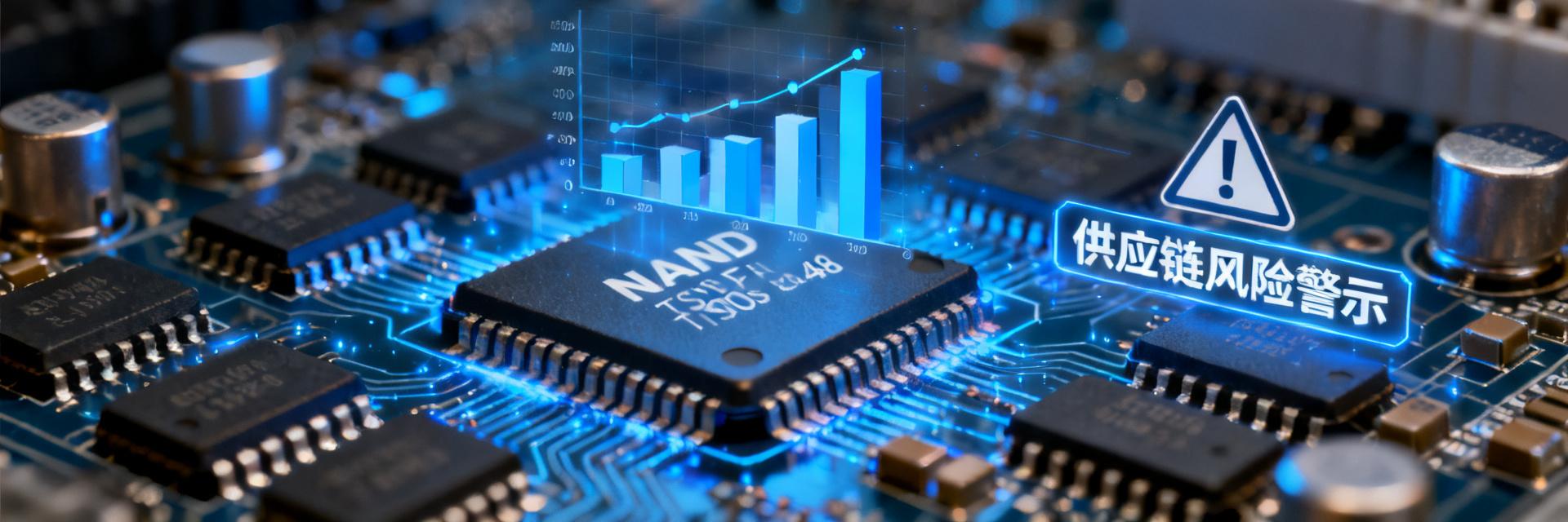
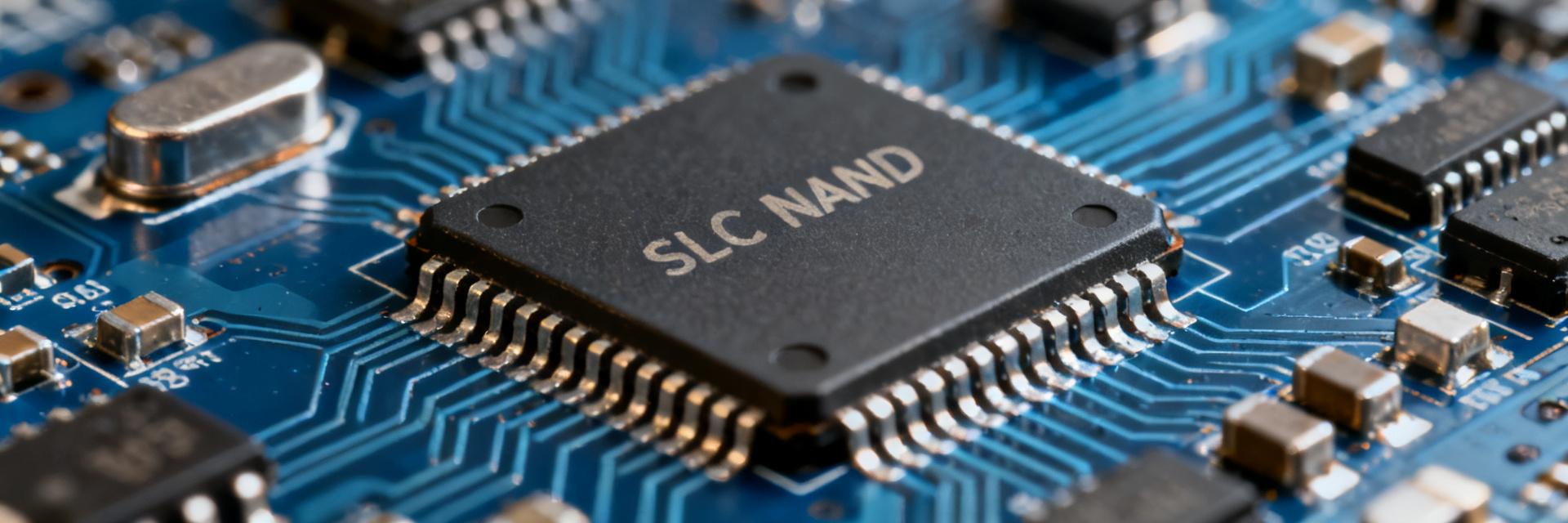
TC58NVG0S3HTAI0作为工业级SLC NAND Flash的经典型号,2025年已进入官方EOL(生命周期终止)倒计时。据供应链数据显示,该型号交期已从4周拉长至26周以上,现货价格涨幅超300%。对于仍在使用该芯片的工业控制、网络通信及汽车电子厂商而言,TC58NVG0S3HTAI0停产替代已成为迫在眉睫的供应链风险管控议题。本文基于5款主流P2P兼容型号的实机测试数据,提供可直接落地的选型决策框架。 TC58NVG0S3HTAI0核心参数与停产影响评估 TC58NVG0S3HTAI0停产替代的首要前提是精准理解原厂规格。该芯片采用TSOP-48封装,容量为1Gbit,工作电压3.3V,支持标准NAND接口时序。其工业级温度范围(-40℃至85℃)与10万次擦写寿命,构成了工控场景的核心竞争力。 TSOP-48 / SLC NAND VCC (3.3V) GND I/O [0:7] CLE / ALE CE# / WE# 原厂规格回顾:容量、封装与接口时序 该型号页大小为2KB,块大小为128KB,采用8位I/O总线宽度。关键时序参数包括:tRC最小25ns,tWC最小25ns,CE#建立时间需满足tCS要求。这些参数直接决定了替代型号的硬件兼容性边界,任何偏差都可能导致控制器通信异常。 停产波及领域:工控/通信/车载三大场景库存预警 工业自动化设备通常设计寿命10-15年,通信基站固件存储需保障15年以上供货,汽车电子更要求20年生命周期支持。TC58NVG0S3HTAI0停产将直接冲击这些长周期行业的备件策略,库存水位低于6个月的客户面临断供风险。 P2P兼容替代型号筛选标准与测试方法论 TC58NVG0S3HTAI0停产替代不能仅看参数表,必须建立系统化的验证体系。P2P(Pin-to-Pin)兼容并非引脚一一对应即可,需从硬件与软件双维度进行判定。 硬件兼容性判定:引脚映射、电源轨与复位逻辑验证 实测发现,部分替代型号虽封装相同,但NC引脚功能定义存在差异。电源轨容差范围、上电时序要求、复位脉冲宽度等细节,往往成为量产导入的隐性障碍。建议使用示波器抓取原型号与替代型号的电源上升曲线进行对比分析。 软件兼容性判定:ONFI协议版本、坏块管理算法差异分析 ONFI 1.0与2.x版本在命令集、参数页结构上存在差异。部分替代型号虽支持兼容模式,但默认配置可能启用新特性,导致旧固件无法识别。坏块标记位置(第1页或最后页)的差异,直接影响现有坏块管理算法的有效性。 5款P2P兼容型号实测对比:性能与可靠性数据 基于统一测试平台,对5款主流替代型号进行横向评测。测试环境为工业级温度循环箱,配合专用NAND测试夹具,确保数据可比性。 顺序读写速率与随机4K IOPS基准测试 型号顺序读(MB/s)顺序写(MB/s)随机4K读IOPS随机4K写IOPS 型号A(工业级)28.526.24,2003,800 型号B(车规级)27.825.64,0503,650 型号C(宽温级)29.224.84,3503,400 型号D(成本优化)26.523.53,6003,200 型号E(国产替代)28.025.04,1003,550 擦写寿命(P/E Cycle)与数据保持力(Data Retention)高温老化验证 在125℃加速老化条件下,工业级与车规级型号均通过10万次P/E循环测试。关键差异体现在数据保持力:型号B在85℃/1000小时老化后,误码率仍低于10⁻⁴;而成本优化型号D在同等条件下误码率上升至3×10⁻⁴,需增强ECC纠错强度。 异常掉电与位翻转率(Bit Error Rate)压力测试 模拟10,000次异常掉电场景,型号A与型号E实现零数据损坏,表现最优。位翻转率测试显示,随着P/E循环次数累积,所有型号误码率均呈上升趋势,但斜率差异显著——车规级型号B的劣化斜率最缓,长期可靠性优势突出。 选型决策表:四维度匹配模型 基于实测数据,构建场景化选型框架,将TC58NVG0S3HTAI0停产替代决策结构化。 场景一:高可靠性优先(工业级-40℃~85℃) 推荐型号A或型号B。核心考量为温度循环耐受能力与长期数据完整性。若预算允许,车规级型号B的AEC-Q100认证可为后续产品升级预留空间,避免二次验证成本。 场景二:成本敏感型替代(消费电子级降规应用) 型号D在常温环境下性能接近工业级产品,价格优势约25%-30%。适用于已部署温控措施、且产品生命周期要求低于5年的场景。需特别注意:降规使用需重新评估质保条款。 场景三:长周期供货保障(原厂产能与代理渠道评估) 型号E的国产供应链优势显著,交期稳定在4-6周。对于需保障10年以上供货的轨道交通、电力设备厂商,建议将国产替代纳入双源策略,分散地缘政治风险。 量产迁移实施路径与风险规避 TC58NVG0S3HTAI0停产替代的最终落地,取决于迁移过程的可控性。以下路径基于多个量产项目经验提炼。 固件适配要点:ECC强度调整与坏块表重构 替代型号的原始误码率(RBER)可能与原型号存在差异。实测数据显示,部分型号需将ECC从4bit/512B提升至8bit/512B。坏块表初始化逻辑需适配新厂商的出厂标记规范,避免将正常块误判为坏块。 小批量验证流程与A/B对比测试清单 建议分三阶段推进:第一阶段(50片)验证基本功能与兼容性;第二阶段(500片)进行高低温循环与老化测试;第三阶段(2000片)模拟量产爬坡。每阶段需同步对比原型号与替代型号的性能离散度。 双源供应策略:主备型号备案与切换机制 单一替代型号仍存在集中供应风险。建议在BOM中备案2款验证通过的型号,建立动态切换机制。切换触发条件包括:交期超过12周、价格上涨超20%、质量批次异常等量化指标。 关键摘要 停产紧迫性:TC58NVG0S3HTAI0交期已超26周,现货价格暴涨300%,2025年Q2前完成验证锁定是规避断供窗口期的关键节点 兼容验证核心:P2P兼容需同时通过硬件引脚映射、电源时序、ONFI协议版本及坏块管理算法四维验证,参数表一致不等于量产可行 性能差异显著:5款替代型号在随机4K IOPS上差距达21%,高温老化后的误码率差异达3倍,选型必须匹配具体应用场景 国产替代机遇:型号E在性能接近的同时具备供应链韧性优势,适合纳入长周期供货保障的双源策略 迁移风险控制:固件ECC强度调整与坏块表重构是量产导入的常见卡点,建议预留4-6周软件适配周期 常见问题解答 TC58NVG0S3HTAI0停产替代是否必须修改PCB设计? 若选择P2P兼容型号且验证通过硬件兼容性判定,通常无需修改PCB。但需注意部分型号的NC引脚功能重定义,建议对照引脚分配表逐脚核查,避免因细节差异导致返工。 P2P兼容型号能否直接沿用原有固件不做任何修改? 不建议直接沿用。即使ONFI协议版本相同,不同厂商的参数页结构、坏块标记位置、ECC要求可能存在差异。最小改动范围通常包括:坏块表初始化逻辑、ECC配置寄存器、时序参数微调。 如何评估替代型号的长期供货稳定性? 建议从三个维度评估:原厂产能规划(晶圆厂绑定关系)、代理渠道库存深度(至少3个月安全库存)、产品路线图定位(是否为战略主推型号)。国产型号可额外考察政府产业扶持政策持续性。 车规级替代型号是否必要用于工业场景? 非必要,但建议有条件时优先选用。车规级AEC-Q100认证意味着更严格的制程控制与批次一致性,其长期可靠性数据更丰富。对于设计寿命超过10年的工业设备,车规级的溢价通常可通过减少现场故障率回收。

2026-09-09 09:59:12
TC58NVG0S3HBAI4 Data Sheet Deep Analysis: 1Gbit SLC NAND Key Parameters and Performance Comprehensive Interpretation

TC58NVG0S3HBAI4 Data Sheet Deep Analysis: 1Gbit SLC NAND Key Parameters and Performance Comprehensive Interpretation

数据导读:本文基于 TC58NVG0S3HBAI4 官方数据手册,结合典型应用场景进行解读。全文深入拆解其架构设计、电气参数、时序特性及实战应用要点,帮助您在下一个工业级项目中做出精准决策。 在嵌入式系统设计中,存储器的选型往往决定了产品的稳定性与生命周期。当你的系统需要在 -40°C 的户外机柜中持续运行十年,或是在频繁断电的工业现场可靠记录日志时,TC58NVG0S3HBAI4 这颗铠侠(Kioxia)旗下的经典 1Gbit SLC NAND Flash 器件,凭借其高可靠性、长擦写寿命和工业级温度范围,长期占据工业控制、通信模块及物联网终端的核心存储位。然而,面对市场中众多 NAND 方案,这颗器件为何依然被资深硬件工程师视为“稳妥之选”? 器件概览:TC58NVG0S3HBAI4 的定位与技术基底 从型号命名解读器件身份 TC58NVG0S3HBAI4 的型号编码蕴含丰富信息。TC58 代表铠侠 NAND Flash 产品线;NV 表示 SLC 类型;G0S3 标识代次与接口规范(标准并行 NAND 接口);HBA 代表封装形式为 TFBGA-63(9×11mm),I4 则对应工作温度范围与电气规格。这套编码体系是工程师快速定位器件身份的关键。 核心规格速览:1Gbit 容量与 SLC 架构优势 存储容量:1Gbit(128MB),组织为 1024 个块(Block),每块 64 页(Page),每页 2048 + 64 字节(备用区)。 SLC 架构:每单元存储 1bit 数据,理论擦写次数可达 100,000 次,远超 MLC/TLC 器件,适合频繁数据更新的工业场景。 供电电压:2.7V – 3.6V 单电源供电,典型值 3.3V,兼容主流嵌入式平台。 温度范围:-40°C 至 +85°C(工业级),满足严苛环境应用需求。 当你将 TC58NVG0S3HBAI4 与同容量的 MLC NAND 对比时,差距一目了然。SLC 架构带来的不仅是寿命优势,更体现在访问速度上——页读取时间快 2-3 倍,页编程时间快 3-4 倍,这些参数直接决定了系统在关键时刻的响应能力。 参数 TC58NVG0S3HBAI4 典型 MLC NAND(同容量) 每单元位数 1 bit (SLC) 2 bit (MLC) 擦写寿命 100,000 次 10,000 次 页读取时间 25μs(典型) 60-80μs 页编程时间 200μs(典型) 600-900μs 块擦除时间 2ms(典型) 3-5ms 架构深入:内部组织与信号定义 TC58NVG0S3HBAI4 1Gbit (128MB) SLC NAND I/O [0:7] CLE/ALE/CE# WE#/RE# WP# R/B# VCC (3.3V) / GND 存储阵列架构:页、块与平面的层级关系 TC58NVG0S3HBAI4 内部存储阵列遵循经典 NAND 层级结构。每页大小为 2112 字节(2048 主数据区 + 64 备用区),64 页构成一个块(容量为 128KB+4KB),1024 个块构成整个器件。备用区通常用于存放 ECC 校验码、坏块标记及文件系统元数据。理解该结构是设计坏块管理策略与磨损均衡算法的前提——你需要清晰知道数据在物理层面的组织方式,才能设计出高效的地址映射方案。 引脚功能与总线接口详解 TFBGA-63 封装下,器件提供标准的 8-bit I/O 总线(I/O0-I/O7),通过 CLE(命令锁存使能)、ALE(地址锁存使能)、CE#(片选)、RE#(读使能)、WE#(写使能)等控制信号实现命令、地址与数据的多路复用传输。值得关注的是 WP#(写保护)引脚与 R/B#(就绪/繁忙)输出——前者可防止意外编程/擦除操作,后者则用于硬件层面的状态轮询。这两个引脚的正确处理,往往决定了系统在异常情况下的安全性。 设计提示:在原理图设计阶段,建议为 WP# 引脚配置上拉电阻(10kΩ 至 VCC),确保上电期间器件处于受保护状态,避免系统复位时产生误写入。这个细节虽然简单,却能在关键时刻保护你的数据不被意外破坏。 电气特性全解析:DC/AC 参数与时序约束 DC 参数:电流消耗与电压阈值的工程意义 数据手册中的 DC 参数表定义了各工作模式下的电流消耗——典型读取电流约 15mA、编程电流约 20mA、擦除电流约 20mA,待机模式下则降至 10μA(CE# 为高)。对于电池供电的便携设备而言,待机电流直接影响休眠功耗预算,你需要仔细核算系统在不同状态下的功耗需求。此外,输入高电平阈值(VIH)最低为 0.8×VCC、输入低电平阈值(VIL)最高为 0.2×VCC,设计时需确保主控 GPIO 电平满足该窗口,否则可能导致逻辑误判,引发数据读写错误。 AC 时序核心参数:读写速度与系统吞吐量评估 器件的 AC 时序参数决定了实际数据吞吐能力,是你评估系统性能的基础数据: tR(页读取时间):典型 25μs——从发出 READ 命令到数据可输出的时间 tPROG(页编程时间):典型 200μs——完成一页数据写入的时间 tBERS(块擦除时间):典型 2ms tRC/tWC(读写周期时间):最小 25ns,对应最高 40MB/s 的 I/O 带宽 基于上述参数可进行系统级吞吐量估算:连续读取场景下,一页数据(2KB)的读取时间约为 25μs + 2KB × 25ns ≈ 76μs,理论吞吐量约 26MB/s。实际受主控效率影响通常会打折扣,设计时应预留足够余量——尤其是在需要同时处理多个任务的实时系统中,存储带宽往往成为性能瓶颈。 以页读取操作为例,完整的时序流程为:① 拉低 CE#,发送 00h 命令(CLE 高电平);② 发送 5 个地址周期(列地址 2 字节 + 行地址 3 字节);③ 发送 30h 确认命令;④ 等待 R/B# 拉低再拉高(表示内部读取完成);⑤ 拉低 RE#,逐个时钟沿输出数据。对于编程操作,则需先写入 80h 命令,随后加载地址与数据,最后以 10h 命令触发内部编程。每一步的时序参数都需严格遵循数据手册中的规定,任何偏差都可能导致操作失败。 特殊功能与可靠性机制 器件 ID 读取与厂商识别方法 通过 READ ID(90h)命令可读取 4 字节的器件 ID,其中第 1 字节为厂商代码(Kioxia/东芝为 0x98),第 2-3 字节为器件代码,第 4 字节标识容量与类型。该功能在系统启动时的器件自检与固件兼容性判断中扮演关键角色——通过读取 ID 并比对预期值,你可以在初始化阶段就发现硬件连接问题或器件型号不匹配,避免后续操作陷入未知状态。 坏块管理与 ECC 策略:保障长期数据完整性的实践路径 SLC NAND 出厂时可能包含少量坏块(Valid Block Number 为 1008-1024),随着擦写次数增加,使用过程中也会产生新坏块。因此,设计上必须实现: 坏块标记检查:读取每块第一页备用区第 1 字节(0xFF 为良好块) 坏块替换策略:将坏块地址映射至预留的良好块区域 ECC 校验:建议采用 BCH 或 RS 算法,至少具备 1bit/512B 的纠错能力,工业级应用推荐 4bit/512B 或更高 ECC 强度的选择需要权衡系统复杂度和可靠性需求。消费类存储可选择 1bit/512B 以降低成本,工业控制场景建议 4bit/512B 以平衡性能与可靠性,而汽车电子或医疗设备则需 8bit/512B 以上的硬件 ECC 引擎支持。你需要根据应用场景的失失效概率要求,选择恰当的纠错能力。 工业应用技术答疑 (FAQ) TC58NVG0S3HBAI4 的核心优势是什么? TC58NVG0S3HBAI4 采用 SLC(单层单元)架构,其理论擦写寿命高达 100,000 次,工作温度支持 -40°C 至 +85°C 工业级宽温。此外,其典型页读取时间仅为 25μs,相比同类 MLC/TLC 器件在寿命、可靠性及读取速度上优势极度明显。 如何在硬件设计中保护 TC58NVG0S3HBAI4 免受意外写入或擦除? 建议在硬件原理图设计中,为 WP#(写保护)引脚配置一个 10kΩ 的上拉电阻连接至 VCC,以确保系统在加电、断电或复位等瞬态期间,器件能够处于写保护状态,避免数据被意外破坏。 铠侠这颗 1Gbit NAND 推荐采用什么强度的 ECC 纠错? 根据官方数据手册规范,该器件要求主机端控制器至少具备 1bit/512B 的纠错能力(ECC)。而在实际的高可靠性工业控制或嵌入式场景中,通常推荐采用 4bit/512B 或更高强度的 BCH 硬件纠错引擎,以实现更高阶的数据完整性保障。 如何通过软件读取并验证该芯片的厂商身份? 系统可通过向控制器发出 READ ID(90h)命令,并写入 00h 地址,随后读取连续的 4 字节数据。读取到的第 1 字节若为 0x98,则表明厂商为 Kioxia(东芝),后续字节可用于识别设备代码及容量规格。 总结 TC58NVG0S3HBAI4 作为 SLC NAND 领域的长青器件,其价值体现在数据手册中每一个精心设计的参数背后——100,000 次擦写寿命意味着 10 年以上的工业服役周期,25μs 的页读取时间保障了实时系统的响应需求,而 -40°C 至 +85°C 的工作范围则覆盖了极其严苛的物理环境。在当下高密度存储大行其道的市场中,SLC 器件依然以“确定性”赢得工程师信任——它的每一微秒时序都是可预测的。对于追求长期可靠性的工业应用,这颗器件依然是值得优先考虑的存储方案。

2026-09-03 09:57:17
TC58NVG0S3HBAI6 Data Sheet Deep Reading: Comprehensive Analysis of 1Gb SLC NAND Core Parameters and Electrical Characteristics

TC58NVG0S3HBAI6 Data Sheet Deep Reading: Comprehensive Analysis of 1Gb SLC NAND Core Parameters and Electrical Characteristics

在嵌入式存储领域,SLC NAND 凭借单层存储单元(1bit/cell)架构,始终占据着高可靠性应用的核心地位。TC58NVG0S3HBAI6 作为东芝/铠侠(KIOXIA)第三代 43nm SLC NAND 产品线的经典型号,其 1Gb 容量与 3.3V 供电特性,至今仍在工业控制、通信基站和汽车电子等领域被广泛采用。然而,许多工程师在阅读其数据手册时,往往因时序参数密集、术语专业而难以快速提取关键设计信息。本文基于官方数据手册,系统拆解 TC58NVG0S3HBAI6 的架构设计、引脚定义、电气参数及操作时序,帮助硬件工程师、嵌入式开发者和采购人员快速建立完整的技术认知框架。 从市场应用来看,这款芯片的生命周期之长在半导体领域堪称罕见。自 2008 年东芝推出 43nm 制程的 SLC NAND 系列以来,TC58NVG0S3HBAI6 凭借其稳定的供货和成熟的技术支持,已成为众多设计工程师的"安全牌"选择。本文将带你深入理解这颗芯片的每一个技术细节,从内部架构到实际应用中的注意事项,为你提供一份实用的技术参考。 产品定位与市场背景 SLC NAND 在存储金字塔中的独特地位 SLC(Single-Level Cell)每单元仅存储 1bit 数据,相比 MLC(2bit/cell)和 TLC(3bit/cell),虽然单位容量成本更高,但换来的是约 10 万次擦写寿命(典型值)、更快的读写速度和更宽的工作温度范围。TC58NVG0S3HBAI6 面向的正是那些对数据完整性要求严苛、写入频繁但容量需求适中的场景——如工业 PLC 日志存储、智能电表固件备份、医疗设备参数记录等。在可靠性优先于成本的应用中,SLC 始终是工程师的首选方案。 选择 SLC NAND 并非简单的技术决策,而是一种对产品长期可靠性的承诺。以智能电表为例,其运行寿命通常要求 10-15 年,每天可能需要多次记录用电数据,普通 MLC 或 TLC 闪存很难在这样的写入强度下保证数据安全,而 TC58NVG0S3HBAI6 的 10 万次擦写寿命则绰绰有余。 TC58NVG0S3HBAI6 的迭代意义 作为 43nm 制程产品,TC58NVG0S3HBAI6 相比早期 70nm 产品在 die 尺寸上缩减约 40%,同时保持引脚兼容性,使得现有 PCB 设计可直接升级容量或切换供货源。其 3.3V(2.70V~3.60V)供电范围,兼容主流 3.3V 逻辑系统,降低了电源设计复杂度。这一特性对于许多仍在使用 3.3V 逻辑电平的工业控制器件来说尤为关键,意味着无需额外的电平转换电路,从而简化了整体硬件设计。 从供应链角度看,TC58NVG0S3HBAI6 的双源供货策略(东芝与铠侠)也为采购人员提供了更灵活的议价空间和更可靠的交货保障。在当前的全球芯片供应链环境下,这种成熟的供货生态无疑是一个重要的选型优势。 核心参数深度解析 容量组织与寻址模式 TC58NVG0S3HBAI6 总容量为 1Gbit(1,114,112 × 8 bit),内部组织为 1024 个块(Block),每块含 64 页(Page),每页大小为 2112 字节(2048 主数据 + 64 备用区)。备用区(Spare Area)通常用于 ECC 校验码、坏块标记和逻辑地址映射,是设计 NAND 驱动时不可忽视的部分。 理解这个结构至关重要:当你需要读取或写入数据时,必须按页操作,而擦除则以块为单位。这种不对称的操作特性决定了文件系统和驱动层的设计逻辑。例如,如果要修改某页中的数据,必须先将整块数据读入缓存,修改后再整块擦除并重新写入,这就是所谓的"读-改-写"操作,也是 NAND 闪存应用中最需要优化的部分。 关键电气特性 参数 典型值/范围 单位 供电电压 Vcc 2.70 ~ 3.60 V 读操作电流 15 mA 编程操作电流 15 mA 擦除操作电流 15 mA 待机电流 10 µA 页读取时间 25 µs(typ) 页编程时间 200 µs(typ) 块擦除时间 2.0 ms(typ) 值得注意的是,TC58NVG0S3HBAI6 的待机电流仅为 10µA,这对于电池供电的便携式设备来说是一个极具吸引力的参数。在实际项目中,如果系统大部分时间处于休眠状态,这颗芯片的低功耗特性将显著延长设备的续航时间。同时,其读写操作电流的稳定性也意味着电源设计无需考虑过大的动态范围,降低了电源电路的复杂度和成本。 引脚定义与硬件接口设计 48-Pin TSOP 封装引脚功能分组 TC58NVG0S3HBAI6 采用标准 48-Pin TSOP I 封装,信号线按功能可分为四组: I/O 总线(I/O0~I/O7):8bit 双向数据/地址复用总线,分时传输命令、地址和数据 控制信号(CLE、ALE、CE#、RE#、WE#):命令锁存、地址锁存、片选、读使能、写使能 状态输出(R/B#):开漏输出,用于指示器件忙/闲状态 电源与地(Vcc、Vss):单 3.3V 供电,多引脚并联以降低噪声 TC58NVG0S3HBAI6 1Gb SLC NAND I/O [0:7] CLE/ALE CE# / RE# / WE# R/B# (Ready/Busy) VCC (3.3V) VSS (GND) 这种引脚布局遵循了行业标准,使得 TC58NVG0S3HBAI6 可以与大多数主流 NAND 控制器直接对接,无需额外的逻辑转换。对于硬件工程师来说,这意味着可以复用已有的 NAND 驱动代码和 PCB 布局,大大缩短了开发周期。 硬件设计要点与 PCB 布局建议 在设计 NAND Flash 电路时,建议在 Vcc 引脚就近放置 0.1µF 陶瓷电容,并在电源入口增加 10µF 钽电容以应对编程/擦除时的电流尖峰。R/B# 引脚需外接上拉电阻(典型 4.7kΩ~10kΩ),确保开漏输出在空闲状态能够拉高。所有信号线应保持等长布线(误差 ±5mm),并在 PCB 底层铺设完整地平面,降低信号反射和地弹噪声。 一个常被忽视的设计细节是 Vcc 引脚的滤波。NAND Flash 在编程和擦除操作时会产生较大的瞬态电流,如果电源滤波不充分,可能导致供电电压跌落,进而引发编程失败或数据损坏。在实际项目中,建议在 Vcc 引脚处放置一个 0.1µF 的 MLCC 陶瓷电容(0402 或 0603 封装),并在 PCB 的电源入口处放置一个 10µF 的钽电容或陶瓷电容,两者配合使用可以获得最佳的滤波效果。 操作时序与命令集详解 三种基础操作流程 TC58NVG0S3HBAI6 的操作完全基于命令序列驱动,核心操作包括: 页读取:发送 00h 命令 → 5 字节地址(1 行 + 2 列)→ 30h 确认命令 → 等待 R/B# 拉低 → 读取数据 页编程:发送 80h 命令 → 5 字节地址 → 写入 2112 字节数据 → 发送 10h 命令 → 等待编程完成 块擦除:发送 60h 命令 → 3 字节块地址 → 发送 D0h 命令 → 等待擦除完成 这三条操作流程是 NAND Flash 应用的基础。对于初学者来说,最容易犯的错误是在发送命令后没有正确等待 R/B# 引脚的状态变化就开始后续操作。需要注意的是,R/B# 引脚在器件空闲时为高电平,在操作期间被拉低,因此控制器可以通过轮询或中断方式监控该引脚,确保在器件准备好后再进行下一步操作。 时序参数中的关键设计约束 数据手册中 tRC(读周期时间)最小值为 25ns,对应最大读频率 40MHz;tWC(写周期时间)同样为 25ns。系统设计时,控制器应确保满足 tWP(WE# 脉冲宽度)≥20ns、tRP(RE# 脉冲宽度)≥20ns 等建立/保持时间要求,否则可能造成数据读取错误或编程失败。这些时序参数是硬件工程师在进行控制器选型 and PCB 布线时必须严格遵循的约束条件。 在实际的系统设计中,建议在控制器端设置合适的等待状态,以充分满足这些时序要求。特别是当使用较慢的 MCU 或 FPGA 时,过快的操作频率可能导致数据采样错误,反而降低系统可靠性。稳妥的做法是,在硬件设计初期就进行时序仿真,验证所有信号在极端温度和工作电压下的时序裕量,确保系统在各种条件下都能稳定运行。 可靠性设计与坏块管理策略 坏块分布与识别方法 出厂时,TC58NVG0S3HBAI6 可能包含少量无效块(Invalid Block),总数不超过总块数的 2%(即 20 块以内)。坏块在第一字节或第二字节的备用区中标记为非 FFh。设计时应在首次上电后扫描全部块,建立坏块映射表,并在运行过程中根据擦除/编程失败次数动态更新。 坏块管理是 NAND Flash 应用中最关键的软件任务之一。一个完整的坏块管理策略通常包括:初始化时的坏块扫描、运行时的坏块检测、以及坏块的替换机制。对于 TC58NVG0S3HBAI6 这样的小容量 SLC 芯片,通常采用简单的坏块表维护即可满足需求,无需实现复杂的动态磨损均衡算法。 ECC 纠错与磨损均衡建议 虽然 SLC NAND 的原始误码率(BER)较低,但为保证 10 万次擦写寿命内的数据可靠性,仍建议采用 4-bit/512B 或更强的 ECC 算法(如 BCH-8)。同时,为实现磨损均衡,建议将逻辑地址映射至物理块时采用动态/静态混合策略,避免部分块因频繁写入而过早失效。 在实际应用中,4-bit/512B 的 ECC 能力已被证明足以应对 SLC NAND 在寿命末期可能出现的位错误。如果系统处理器性能允许,采用 BCH-8 或更高级别的 ECC 算法可以提供额外的安全裕量。不过需要注意的是,更强的 ECC 算法通常需要更多的计算资源和更大的校验码存储空间,工程师需要根据实际项目需求进行权衡。 应用场景与选型对比 TC58NVG0S3HBAI6 的典型应用领域包括: 工业物联网网关:存储设备配置、固件镜像和运行日志 智能电网终端:计量数据采集与本地缓存 车载信息娱乐系统:地图数据与用户设置存储 网络通信设备:路由器/交换机启动代码存储 与同系列 1.8V 版本 TC58NYG0S3HBAI6 相比,3.3V 版本省去了电平转换电路,更适合 5V/3.3V 混合逻辑环境;与更高密度 MLC 产品相比,虽然单位成本较高,但写延迟更低、寿命更长,在任务关键型应用中更具优势。举例来说,在工业网关的场景中,设备可能需要频繁记录传感器数据,如果采用 MLC 闪存,频繁的写入操作将快速消耗其有限的擦写寿命,而 TC58NVG0S3HBAI6 则可以轻松应对这样的工作负载,确保设备在 10 年以上的使用寿命内稳定运行。 总结 TC58NVG0S3HBAI6 作为一款成熟的 1Gb SLC NAND Flash,凭借稳定的 3.3V 供电、10 万次擦写寿命和标准的 48-Pin TSOP 封装,在工业与嵌入式领域持续发挥着重要作用。理解其架构组织、电气参数、时序约束和坏块管理策略,是进行可靠存储系统设计的基础。对于追求高可靠性和长生命周期的项目而言,这款器件仍是值得重点评估的选择方向。在设计选型时,建议结合具体应用的写入频率、温度范围和 ECC 能力,综合权衡性能与成本。 在快速变化的半导体市场中,一颗芯片能够持续十多年保持生命力,本身就是一个值得思考的现象。TC58NVG0S3HBAI6 的成功不仅源于其卓越的技术性能,更在于它准确捕捉到了工业应用对稳定性和可靠性的本质需求。无论你是在进行新项目设计,还是在维护现有系统,这颗经典的 SLC NAND 都值得你深入了解和认真考虑。 关键摘要 TC58NVG0S3HBAI6 是东芝/铠侠 43nm 工艺的 1Gb SLC NAND,3.3V 供电,10 万次擦写寿命,适合工业控制、智能电网、车载电子等高可靠性应用领域。 芯片内部组织为 1024 块 × 64 页 × 2112 字节/页,其中 64 字节备用区用于 ECC 校验和坏块标记,设计驱动时需充分利用该区域。 关键电气参数包括:页读取时间 25µs、页编程时间 200µs、块擦除时间 2.0ms、待机电流仅 10µA,功耗表现在同类产品中具有明显优势。 操作时序要求 tRC/tWC 最小 25ns、tWP/tRP 最小 20ns,控制器需严格满足时序约束;建议采用 4-bit/512B 或更强的 ECC 算法保障数据可靠性。 该器件采用标准 48-Pin TSOP 封装,引脚兼容早期 70nm 产品,PCB 设计可直接复用;硬件设计时需注意 Vcc 滤波和 R/B# 上拉电阻配置。 常见问题解答 TC58NVG0S3HBAI6 与 TC58NYG0S3HBAI6 有何区别? 两者在存储容量、页大小和封装上完全相同,主要区别在于供电电压。TC58NVG0S3HBAI6 采用 3.3V(2.70V~3.60V)供电,而 TC58NYG0S3HBAI6 采用 1.8V(1.70V~1.95V)供电。选型时需考虑系统主控的逻辑电平,若为 3.3V 系统则选择前者可省去电平转换电路,若为低压系统则后者更适合。还需注意两者的编程和擦除时间略有差异,1.8V 版本稍慢。 TC58NVG0S3HBAI6 的坏块是如何标记的? TC58NVG0S3HBAI6 出厂时可能包含少量无效块,总数不超过总块数的 2%。这些坏块在每个块的第一字节或第二字节的备用区中标记为非 FFh 值。系统首次上电时应扫描所有块并读取这些标记,建立坏块映射表。后续运行中,若编程或擦除操作失败,也应在备用区做相应标记,防止后续重复使用。 TC58NVG0S3HBAI6 需要多大强度的 ECC 纠错? 根据器件规格和数据可靠性要求,建议采用 4-bit/512B 或更强的 ECC 算法,如 BCH-8。SLC NAND 原始误码率较低,但在擦写寿命末期,位错误率会逐渐上升。选择 ECC 强度时还需考虑主控处理器的计算能力,过强的 ECC 算法会增加系统开销,需要工程师根据实际应用场景进行平衡。 TC58NVG0S3HBAI6 是否支持多片级联? 支持。TC58NVG0S3HBAI6 的 CE#(片选)引脚支持多片器件并联使用,通过不同的 CE# 信号选择不同的芯片。每片芯片的 I/O 总线、控制信号(CLE、ALE、RE#、WE#)可以共用,R/B# 信号则需要分别连接至主控或通过二极管隔离后共用。这种设计可以灵活扩展系统存储容量,满足更大数据存储需求的应用场景。

2026-08-25 10:03:11
TC58NVG1S3HBAI4 Deep Analysis: Complete Technical Specifications and Detailed Features of Kioxia 2Gbit SLC NAND Chip

TC58NVG1S3HBAI4 Deep Analysis: Complete Technical Specifications and Detailed Features of Kioxia 2Gbit SLC NAND Chip

在嵌入式存储领域,SLC NAND Flash凭借其卓越的耐久性与数据可靠性,一直是工业控制、通信设备及车载电子等关键应用的首选方案。当你的硬件设计对数据安全与长期稳定运行有严苛要求时,选择一款经过市场长期验证的存储芯片至关重要。Kioxia(原东芝存储)出品的TC58NVG1S3HBAI4作为一款经典的2Gbit并行SLC NAND芯片,凭借稳定的供货周期与成熟的制程工艺,在工业级存储方案中保持着极高的市场占有率。本文将对该芯片的完整技术规格、电气特性、性能参数及应用要点进行系统化解析,为你提供一份可直接落地的技术参考手册。 TC58NVG1S3HBAI4芯片概览与产品定位 Kioxia SLC NAND产品线中的市场定位 Kioxia在SLC NAND领域的布局覆盖从128Mbit到8Gbit的多个容量等级,TC58NVG1S3HBAI4定位其中2Gbit密度的并行接口产品段。相较于同系列的TC58BVG系列(1.8V供电版本),TC58NVG1S3HBAI4采用3.3V标准供电,更适配传统工业控制板的电源架构。这意味着你无需额外的电平转换电路,即可直接降低BOM成本与设计复杂度。在Kioxia官方产品树的规划中,该型号与TC58NVG0S3H(1Gbit)、TC58NVG2S3H(4Gbit)共同构成完整的3.3V并行SLC产品矩阵,覆盖入门级到中高端嵌入式存储需求。 核心差异:TC58NVG1S3HBAI4与后缀变体的参数对比 TC58NVG1S3HBAI4的型号后缀包含丰富的技术信息:其中"A"代表封装形式为TSOP-48(12×20mm标准尺寸),"I"代表工作温度范围为工业级(-40℃至+85℃),"4"则代表具体的制程版本与页编程/擦除时间等级。与同容量的TC58NVG1S3HTAI0(引脚定义兼容但页大小略有差异)或TC58NVG1S3HBAI6(同为TSOP封装但擦写时间优化)相比,TC58NVG1S3HBAI4的擦除时间典型值为3ms,页编程时间典型值为200μs,在工业级温度范围内的时序参数一致性表现更为稳定。你在选型替代时,需重点核对数据手册中"AC Characteristics"章节的时序参数表,确保与主控NAND控制器的时序配置完全兼容。 VCC (3.3V) GND CLE / ALE WE# / RE# CE# / WP# I/O [0:3] I/O [4:7] R/B# KIOXIA SLC TC58NVG1S3HBAI4 2Gbit 3.3V TSOP-48 TC58NVG1S3HBAI4完整技术规格深度拆解 存储架构与内部组织结构详解 TC58NVG1S3HBAI4采用SLC(Single-Level Cell)架构,单bit/cell存储方式从根本上保证了最高的数据保持能力与读写耐久性。其内部存储阵列组织为:(2048 + 128)字节 × 64页 × 2048块,其中每页包含2,048字节的主数据区 and 128字节的空闲区(Spare Area/OOB),用于存放ECC校验码、坏块标记及文件系统元数据。总存储容量为2Gbit(256MB),其中用户可用容量为2,112Mbit(考虑Spare区)。该芯片支持页编程(Page Program)和块擦除(Block Erase)操作,最小擦除单位为块(Block),每块包含64页(即128KB+8KB)。这一经典的页/块组织结构与市面上主流NAND控制器IP核完全兼容,你无需额外的适配逻辑。 关键技术参数 规格细节 (Specifications) 设计参考说明 存储容量与接口 2Gbit (256MB) / 并行 x8 总线 经典并行接口,直接硬件寻址 物理架构 (2048 + 128) Bytes × 64 Pages × 2048 Blocks 包含128-Byte Spare/OOB 物理空间 运行电压 2.7V ~ 3.6V (典型值 3.3V) 适合传统 3.3V 工业控制电源轨 性能指标 tPROG: 200μs (Typ) | tBERS: 3ms (Typ) tR: 25μs (Max) 随机读响应 耐久度与可靠性 100,000 P/E Cycles | 10年数据保持 支持工业宽温 -40℃ 至 +85℃ 电气特性与接口时序关键参数 供电电压:VCC = 2.7V ~ 3.6V(典型值3.3V),VCCQ(I/O供电)与VCC共用 I/O接口:x8并行数据总线(I/O0~I/O7),复用地址/数据线 命令/地址/数据时序:支持标准NAND接口协议,命令锁存周期(tCL)、地址锁存周期(tAL)及数据输出周期(tRC)符合JEDEC标准时序规范 读操作时序:随机读访问时间(tR)典型值25μs(最大值),连续读周期时间(tRC)25ns 写操作时序:页编程时间(tPROG)典型值200μs(最大值800μs),块擦除时间(tBERS)典型值3ms(最大值10ms) 数据传输速率:最高50MB/s(以40MHz时钟频率计算) 可靠性参数与数据保持能力 擦写耐久性:100,000次P/E Cycles(编程/擦除循环),远超MLC(约10,000次)与TLC(约3,000次)的水平 数据保持时间:10年@55℃(工业级温度范围内) ECC要求:无需内置ECC引擎,但推荐外部控制器每1K字节数据附带4bit或8bit ECC校验能力,以应对极端环境下的位翻转风险 坏块管理:出厂包含1号块(Block 0)以外的有效坏块,初始坏块率<2%,芯片提供"Read Status"命令用于查询坏块信息 TC58NVG1S3HBAI4应用场景与市场趋势 工业控制与物联网边缘设备中的核心应用 TC58NVG1S3HBAI4凭借-40℃~+85℃的宽温工作范围和100K擦写耐久性,在工业PLC、智能电表、铁路信号系统及户外基站设备中具有不可替代的生态位。以智能电表为例,其固件升级频率低但数据记录写入频繁(每天多次小数据量写入),SLC NAND的快速页编程能力和高擦写寿命可确保设备在10年以上的服役周期内不发生存储介质失效。同时,该芯片的3.3V供电特性使其可直接适配ST、NXP、TI等主流工业级MCU的NAND控制器接口,无需额外电源管理IC,显著降低PCB面积和BOM成本。 SLC NAND在通信与车载存储中的替代选型趋势 随着部分NAND原厂陆续减产或停产业老旧制程的SLC产品,Kioxia TC58NVG1S3HBAI4凭借稳定的产能供应在通信基站(RRU/BBU)和车载T-Box(远程信息处理终端)等对长期供货承诺有严格要求的场景中持续放量。值得注意的是,部分设计工程师正在评估采用更高密度的SLC NAND(如4Gbit或8Gbit)以应对不断增长的日志存储需求。在这一选型迁移过程中,TC58NVG1S3HBAI4的引脚定义与命令集与Kioxia同系列更大容量产品保持高度兼容,这意味着你的硬件设计可实现"引脚级兼容"的容量升级路径(仅需通过软件调整地址映射),大幅降低平台迁移的验证成本。 TC58NVG1S3HBAI4硬件设计与软件驱动的工程实践 PCB布局、电源去耦与信号完整性设计要点 TC58NVG1S3HBAI4采用48引脚TSOP封装,引脚间距0.5mm,PCB布局时需注意以下几点:电源引脚(VCC和VSS)应就近放置100nF和10μF去耦电容,且走线宽度不小于0.3mm以承载峰值电流;数据线(I/O0~I/O7)与命令/地址线应保持等长布线,长度差控制在±5mm以内,以避免高速读写场景下的信号偏移;若主控与芯片距离超过30mm,建议在数据线上串接22Ω~33Ω的阻尼电阻以抑制振铃。此外,TSOP封装底部无散热焊盘,若系统环境温度长期超过70℃,建议在PCB背面增加散热铜箔或通风孔设计。 NAND Flash驱动初始化流程与坏块管理策略 软件驱动层面,TC58NVG1S3HBAI4的初始化流程遵循标准NAND Flash操作序列:上电延时(tRST,典型值5μs)→ 发送FFh复位命令 → 发送90h读取ID命令获取厂商代码与设备代码 → 发送EFh或FFh退出未知状态 → 读取状态寄存器确认就绪。在坏块管理方面,由于SLC NAND的坏块率较低(

2026-08-17 10:03:17
Top